Leads Direct sell a wide range of Network Cables ready made which you can view and purchase by visiting our secure online shop whch has literally thousands of products each with two sizes of image. Leads Direct can also make custom network cables to your specification on request.
However, there may well be times when you need to make your own or repair an existing installation, and that is the purpose of this page. There is a standard to which Network Cables must be made, and the use of a common colour code prevents problems when moving to different sites or fixing different cables - if everyone uses the same colours there is no possibility of a mistake!
Network cables use modular crimp connectors which are fitted using a special crimp tool, which of course can be purchased from our Secure Online Shopping area and also viewed on our Tools page. You will normally see the modular connectors listed as 'RJ45' connectors. Purists will object strongly to this designation, much as they do when S-Video cables are referred to as 'S-VHS', because it is technically incorrect. In general though as long as we all understand what is meant, I think we can accept that 'a rose by any other name would smell as sweet', as Shakespeare wrote...
From our research we understand that 'RJ' was an American national standard that was created so that a customer with a piece of FCC registered equipment could contact any local telephone company, anywhere in the US, give them the RJ requirement (Registered Jack) indicated on the device and the installer would know exactly how the jack needed to be wired. It had absolutely nothing to do with the size, brand or model of the connector itself; it was how the pins were wired when connecting to the public network (PSTN).
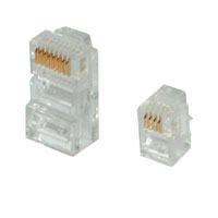 |
Nowadays the term 'RJ45' is used generically to describe the crimp connector that is used for network wiring. In addition there are other modular connectors which also abuse the 'RJ' designation and are used in Telecoms Wiring - RJ10, RJ11, RJ12, RJ22 etc. To the left you will see an image of two standard modular connectors, in this case on the left the one commonly known as RJ45 which has eight positions and eight contacts (8P8C), and on the right the one commonly known as RJ10 or RJ22 which has four positions and four contacts (4P4C). For the avoidance of doubt, we will refer to all connectors in these pages by the correct designation but will include the generic names in brackets beside the designation. In this case, as we are discussing Network connections, the connectors are 8P8C (RJ45) crimp connectors. |
8P8C (RJ45) Modular Connector Numbering
Wiring pinouts refer to pin numbers on the connector in order to ensure that the correct connections are made. However, this is no use at all if you don't know which pins are which! Looking at the top view or 'contact side' of the connector (with the gold metal contacts upwards and directly in front of you, the locking clip underneath) pin 1 is on the left. Subsequent contacts are numbered sequentially from left to right up to pin 8. Looking at the front view, again with the clip downwards, pin 1 is on the right and again the pin numbers run sequentially up to pin 8 except this time from right to left. |
 |
Cable Wiring Pinouts
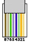
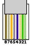
The pin connections are listed below. The diagrams A and B below show the plug with the clip on the under side with the wires entering from the bottom of the connector.
Cat 5e Network Cable Wiring
For standard Cat 5e network wiring, cables should be wired as per Fig 1 (EIA/TIA 568B) and the same at both ends. For Crossover network wiring fit the connectors as per Fig 1 at one end and Fig 2 at the other.
Cat 6 Network Cable Wiring
Cat 6 cabling is normally wired using the same colour code as Cat 5e, although the cable is of a higher specification to allow for higher data transmission speeds.
|
 |
||||||||||||||||||||
Fig 1 |
|||||||||||||||||||||
 |
|
||||||||||||||||||||
Fig 2 |
|||||||||||||||||||||
Connection Hints
For a full step by step tutorial on making modular connections, see our modular connection tutorial page. Otherwise, if you are ready to go it alone, here are some general tips that will help you to get it right...
- It is harder than it looks to get the connection right.
- Make and test practice cables until you get it right every time - it is galling in the extreme if you accidentally destroy a cable that you just spent ages fitting.
- When cutting the exterior cover of the cable be very careful not to cut the insulation cover of the conductors since this can cause connectivity failures that are very difficult to trace.
- Expose a maximum of 25mm of individual conductors when preparing the cable for connection.
- Line up all the conductors according to the wiring standard you are using.
- Measure the cable cores and trim the ends so that they are the correct length for the connector you are fitting.
- Ensure that the cores are all the same length when lined up correctly and that no individual cores are visible outside the plastic cover of the connector. Remember that the cable sleeve should be gripped firmly by the rear grip on the plug - if you do not get this right the connector will be very fragile and will almost certainly break in use.
- Carefully slide the prepared cable into the connector making sure the end of the cores reach right to the end of the connector.
- Using the crimp tool make the connection using one firm squeeze operation.
- If you can, test the cable before fitting.
- The connector is the critical part of the circuit, so always use the highest quality connectors you can afford.
Cable Specifications
The following table defines the properties of each defined cable type (as of July 2004)
EIA/TIA Category |
Speed |
LAN |
100M Support |
ISO Spec |
EIA/TIA Spec |
| Category 3 | 16Mhz | 10Mbit/s | 100Base-T4 | ||
| Category 4 | 20Mhz | 16Mbit/s | 100Base-T4 | ||
| Category 5 (5e) | 100Mhz | 100Mbit/s | 100Base-TX | ISO/IEC-11801 | TIA/EIA-568-A-5 |
| Category 6 | 250Mhz | 100Mbit/s | 100Base-TX | ISO/IEC-11801 | TIA/EIA-568-B.2-1 |
RJ45 to Serial Adaptors
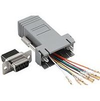
A range of RJ45 socket to Serial adaptors are available from our e-shop in the Computer Adaptors section, with both DB9 and DB25 male and female connections. These do not necessarily have a standard colour scheme but the most common are as follows:
RJ45 to DB9 Male
RJ45 Pin No: |
Colour |
| 1 | Blue |
| 2 | Orange |
| 3 | Black |
| 4 | Red |
| 5 | Green |
| 6 | Yellow |
| 7 | Brown |
| 8 | White |
RJ45 to DB9 Female
RJ45 Pin No: |
Colour |
| 1 | Red |
| 2 | Yellow |
| 3 | White |
| 4 | Green |
| 5 | Blue |
| 6 | Black |
| 7 | Orange |
| 8 | Brown |
If you are seeking information on Network wiring but cannot find it here, please email info@leadsdirect.co.uk and we will try to both answer your question and make sure that the information is made available through these pages for future reference